There seems to have been a drive – since Gillette first started to sell safety razors – to simplify production and increase the profit margin. I’m convinced that not all ideas got patented, but those which did can make for some fascinating reading.
In 1909 Mr Harrison H Boyce put his name on a patent assigned to the Gillette Corp., a patent whose main trust was to reduce the number of parts in a safety razor from four (a cap, a guard, a handle, an a rotary member independent of the handle for securing the guard and cap together) to three. It is – in fact – a patent for what we today can consider the traditional two piece razor – even if it uses a lot of words to explain it.
With the foregoing and other objects in view, which will appear as the description proceeds, the invention resides in a razor construction wherein the handle, instead of serving the sole function of a handle in the usual manner, is caused to serve the two-fold function of a handle and a rotary locking member for drawing the guard and cap together where by the necessity of employing an additional or independent rotary locking member is avoided, and the razor construction is thus implied and rendered less expensive in construction
US patent 917,532 – describing the intention to create a simplified razor
A lot of words for explaining that we’ll put threads at the end of the handle instead of having a knob on the bottom of the razor… but that isn’t all that Mr Boyce included in the patent. One thing is that he imagined a change to the blade geometry – using a single hole as well as cutouts on each end of the blade to align it instead of three holes – another is a rather complex and unnecessary bearing arrangement securing the handle and bottom plate together.
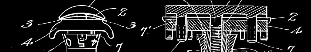
The reference numeral 1 in Figs. 3 and 5 indicates the guard, which preferably is formed along its opposite edges with teeth 2. At the ends thereof the guard i is sit ably cut away to form rectangular recesses 3. The upper surface of the guard preferably is of convex form so as to flex or bend the thin, flat blade 4 in the usual manner. The reference numeral 5 indicates the cap, the lower or under surface of which prefer ably is concave in form to cooperate in the usual manner with the convex upper face of the guard 1 in flexing the razor blade. The cap 5 at the ends thereof is formed with downwardly-extending projections 6, which fit into the recesses 3 in the guard 1, and also engage similar recesses formed in the thin blade for the purpose of holding the blade in position flatwise between the cap and the guard.
US patent 917,532 – describing the blade alignment system
…the guard 1 is formed with a central rabbeted opening 8, in which is rigidly fastened, in any suitable manner, a hard metal ring 9, which preferably is secured in place in the opening 8 by upsetting or expanding its upper end, as shown in Fig. 5. The hard metal ring 9 is stationary with respect to the guard 1 being held in place by its upset end 8, and by its outer periphery which passes under the guard l and forms an external shoulder and serves as a washer for taking up wear. The handle 10 extends at its upper end through the washer 9 and is expanded or enlarged as indicated at 11 so as to provide a swivel joint between the washer 9 and said handle. Below the washer 9 the handle 10 preferably is bulged outward, as shown at 12 in Fig. 5 to complete the swivel joint between the washer 9 and said handle. The inner edge of ring 9 forms a flange which passes between a pair of annular shoulders in the handle formed by the expanded part 11, and the upper surface of bulged portion 12, the said construction permitting a free relative rotation of the parts while preventing a relative longitudinal movement. The handle 10 is internally threaded, as indicated at 13, and is adapted to engage the external threads of a stud 14, which is. rigidly connected in any suitable manner with the cap 5. The stud 14 preferably is hollow, as shown, and is riveted on to the cap 5 as indicated at 15, although it may be otherwise connected therewith if desired. It will be apparent that by rotating the handle 10 in one direction or the other, the cap 5 wWill be moved toward or from the guard 1.
US patent 917,532 – describing in many words how the handle should be connected to the base plate

While containing fewer parts than the original Gillette safety razor, I’m not entirely convinced Mr Boyce’s simplified razor would be all that much cheaper to manufacture… there is a lot of work done to bulge the handle, secure washers to the base plate, and then securing the handle to the washer… but if Mr Boyce had simply reduced the size of the opening in the baseplate to just a little larger than the stud and simply screwed the handle onto the stud, he would have invented the traditional three piece razor – which is as conceptually simple as you can get a DE to be.
Some people might point to the redesigned blades as a pitfall for My Boyce’s razor since Gillette already had invested a lot in machinery for making three hole blades.. but I see no real reason why the head geometry of this here presented razor couldn’t easily been reworked to take those instead.
All in all an interesting old patent, and a glimpse into Gillette’s early attempts at simplifying production and increasing their profit margins.